


L & C Meter (PIC16F84A based)
No self respecting electronics experimenter these days should be without an LC (inductance/capacitance) measuring meter.There are several good designs around; I can thoroughly recommend the product of "electronics - diy" in New York.
If you have a need for such a device I suggest you buy theirs immediately!
Its good value for money, compact, easy to use etc.
The website you need is:
"electronics - DIY.com"
Additionally they will also supply various sections, to allow an experimenter to construct his own
This is exactly what I did, I purchased the pre programmed PIC microcontroller (for abt $US7) and used recycled componentry locally sourced the rest of the electronic hardware.
The enclosure is a metal box salvaged from discarded PC towers, being the switch mode power supply of the computer.
Simply remove the internals (circuit board, fan etc) and you have a 6" x 6" x 3" sized metal box with IEC mains entry connector - ready for re-use.
Blank off any larger holes with scrap metal material.
I have used wire-wrap sockets mounted on a s.r.b.p. (synthetic resin bonded paper) matrix board to facilitate construction of the "electronics" hardware.
The following explains some theory and pictures of my particular "build"
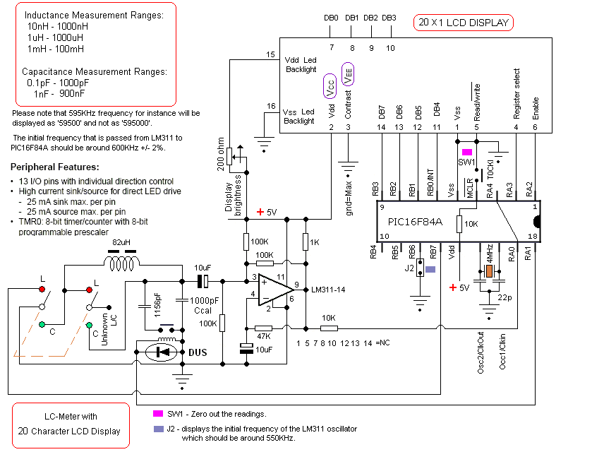
I dispensed with the LCD "contrast" pot' (less than full contrast makes and LCD difficult to see), but included a 200 ohm series "bright" control to reduce the brightness of the display.
I now wonder how I ever managed without such an instrument ?
Previously inductances were merely guess work (by looking at their physical size i.e. RF chokes etc, and capacitors were disgarded if the manufacturers markings had become obscured.)
Now you can easily measure, all kinds of recycled inductors and capacitors and grade/sort/label them, for future re-use.
I had a lot of bakelite encased silver-mica capacitors, which are highly regarded (long life, temp' stability, RF performance, voltage (surge) rating etc) but not of much use if you didn't know their value!

This is one of the most accurate and simplest LC inductance / capacitance Meters that one can find, yet one that you can easily build yourself.
This LC Meter allows to measure incredibly small inductances starting from 10nH to 1000nH,
1uH to 1000uH,
1mH to 100mH
and capacitance from 0.1pF up to 900nF.
LC Meter's circuit uses an auto ranging system so that way you do not need to spend time selecting ranges manually.
Another neat function is the "Zero Out" switch that will reset the initial inductance / capacitance, making sure that the final readings of the LC Meter are as accurate as possible.
Now let's use the above theory and apply it to electronics.
The LC Meter uses a popular LM311 IC that that functions as a frequency generator and this is exactly what we need.
If we want to calculate the value of an unknown inductor we use a known Ccal 1000pF capacitor and the value of an unknown inductor.
LM311 will generate a frequency that we can measure with a frequency meter.
Once we have this information we can use the frequency formula to calculate the inductance.
The same thing can be done for calculating the value of a unknown capacitor.
This time we don't know the value a capacitor so instead we use the value of a known inductor to calculate the frequency. Once we have that information we apply the formula to determine the capacitance.
All this sounds great, however if we want to determine the value of a lot of inductors / capacitors then this may become a very time consuming process.
Sure, we can write a computer program to do all these calculations, but what if we don't have an access to a computer or a frequency meter?
That's were PIC16F84A microchip comes handy.
PIC16F84A is like a small computer that can execute HEX programs that are written using an assembly language.
PIC16F84A is a very flexible microchip because it has PINs which can be configured as inputs and outputs.
Besides that, PIC16F84A IC requires very minimal number of external components like 4MHz crystal / resonator and few resistors depending on what project we are building.
Before we can use PIC16F84A microchip we have to program it with a HEX code which has to be sent from the computer.
In the next step we use the frequency generated by LM311 IC and pass it on to PIC16F84A's PIN 17. We designate this PIN as an input, as well as all other PINs that are directly connected to switches and jumpers.
User can use these inputs to tell the microchip to execute specified set of instructions or perform calculations.
Once the microchip will calculate the unknown inductance or capacitance it will use PINs that are designated as outputs and pass the results on to the 16 character LCD display.
LC Meter's Technical Specifications:
Voltage Supply: 7.5 - 15V
Accuracy: 1%
Zero Out Switch
Automatic Ranging
LC Meter's Inductance Measurement Ranges:
- 10nH - 1000nH
- 1uH - 1000uH
- 1mH - 100mH
LC Meter's Capacitance Measurement Ranges:
- 0.1pF - 1000pF
- 1nF - 900nF
LC Meter's Switches & Jumpers
SW1 - Zero out the readings.
SW2 - Capacitance / Inductance switch.
J1 - used by 16x2 two line character LCD displays.
J2 - displays the initial frequency of the LM311 oscillator which should be around 550KHz.
Most of the character LCD displays have 14 or 16 PINs.
The displays that do have a backlight have 16 PINs and displays that do not have a backlight have 14 PINs.
The PINs that are highlighted in green in the table below are the ones that PIC16F84A uses to pass the output information represented in bits (0/1).
|
The theory behind the measurementsThis section will involve maths and theory.
The LC – meter is actually an LC oscillator based around the familiar comparator circuit LM 311.
We are now dealing with an LC oscillator. The oscillating part is a parallel LC tank.
We will use the well known parallel resonance formula (see formula 1. below).

The formula say that if you connect an inductor parallel with a capacitor, it will have a resonance frequency (f).
L is the inductance in the resonance circuit.
C is the total capacitance in the resonance circuit.
If we connect an unknown capacitor called Cx parallel to C, we will get a lower resonance frequency (f2), due to the increased capacitance.
The formula would then look like this:

As you see, we have a new resonance frequency (f2) and you can see how Cx has been added to C.
Now divide f1 with f2. (formula 3.)

The inductance (L) in the formula has disappeared!
We now have a relationship between capacitances and frequency. (formula 4.)
So what does formula 4 show anyway?
Well, if we know the value of C, and we can measure f1 and f2, we will be able to use formula 4 to calculate Cx.
C is equal to all the parallel capacitance in the LC tank, but we do not know the C of the construction do we?
No we do not, but by making a calibration with a well known Cx, we can go backward and calculate C.
Before any measurement can be done, the LC meter need to perform a calibration to find out the constant value of C.
To find C, we use the formula 4 and break out C. (formula 5.)
The procedure start to measure f1 when only C exist.
Then we add a well known capacitor Cx (reference capacitor) to the LC unit and measure the frequency again (f2).

Since we know Cx (reference capacitor) and we have measured both f1 and f2, the micro controller will be able to calculate the constant value of C.
The procedure above is called the calibration phase.
In reality it is very easy, all you need to do is to press a button called calibrate and the micro controller handles it all for you!
What is important is that you use a very good capacitor for the calibration, else you will add error to measurement.
In my construction I use 1 nF 0.5%. The calibration capacitor will be added automatically with a relay. (more info later)
Now, when the micro controller knows the constant value of C, you can use formula 4 to measure any unknown capacitor at Cx.
Practical example:
To make this even more understandable, I will make a small calculation example to verify the calibration formula:
When I have no capacitor (Cx) connected to my LC-oscillator, I measure 610331Hz.
I connect a well known capacitor (Cx) of 1 nF 0.5% to the LC-oscillator and now the frequency drop to 508609 Hz.
Let’s use the calibration formula 5, above to calculate the value of C in the LC unit.
f1 = 610331, f2 = 508609 Hz, Cx = 440pF. The formula gives C to be 1 nF.
(remember that C is constant and equal to all the parallel capacitance in the LC tank)
Now, when I know C, let’s check if our calculation is correct.
In my measuring example I had an inductor of 68uH in the LC-oscillator.
I use the parallel resonance formula 1 :
When no Cx capacitor is connected I have L= 68uH and C=1000 pF, this gives resonance frequency = 610 331 Hz
When Cx capacitor is connected I have L= 68uH and C=1000 pF + Cx = 440pF, this gives resonance frequency = 508609 Hz
If we compare the calculated frequencies with the measured we can see that the calculation of C = 1000pF was correct. Great!
Now when we know the value of C, we can use formula 4, to measure any unknown value of Cx.
Lets look at the theory how to measure inductance.
We will still use the parallel resonance formula (formula 1,) but in this case we will add an unknown inductance Lx in serial with the L1.

We will have two states.
One when we only have the main inductor L1 connected with C, and a second state when we have the extra inductor Lx in serial with L1.
As you understand we will get two different resonance frequencies.
First state is when I only have L1 connected to C, and the frequency f1 will be produced from the LC-oscillator.
Formula 6 show you how I break out L1 from the parallel resonance formula. Only L1 exist. (Lx = 0)
Second state is when I add Lx in serial with L1 to form L2. Since the inductance increase the frequency (f2) will be produced from the LC-oscillator.
Formula 7 show you how I break out L2 from the parallel resonance formula. L1 and Lx are connected in serial to form L2
What we search for is Lx. (formula 8.). I put formula 6 and 7 into formula 8 and get formula 9.
After cleaning up we get formula 10. Let's look at this formula in more details. As you can see the main inductor L1 is gone.
To measure Lx, we only need to know the C, f1 and f2 of the LC-oscillator.
Conclusion:
It is possible to measure both capacitance and inductance as long as you have an accurate reference capacitor Cx for calibration of your measuring LC-meter.
When it is calibrated you can connect either an unknown capacitor or inductor and measure its value. In this construction I have implemented the calibration so you only need to push a button. The microcontroller will then do all the work for you.
Once again I have plaigarized heavily in order to produce this article.
So credit must go to the following
Ref 1. Electronics - DIY in New York
Ref 2. "RF candy" in Sweden
Ref 3. Capacitance measurement using soundcard of a PC (in German language)
Ref 4. Inductance measurement using soundcard of a PC (in German language)
Addendum Jan 2013
If you can't see youself fabricating an example; as per above, then;
the Chinese are producing good cheap examples of L-C-F meters.
This is typical of many cheap listings found on Ebay: (click to enlarge)


